
Micro-servos are great devices perfect for adding motion to your projects. Unlike steppers, they can be controlled directly from your Arduino or other favorite microcontroller. Most servos are limited to 180 degrees of motion.

This allows microcontrollers to know the exact position of the servo's shaft. You can find continuous rotation servos, but if you have access to lots of cheap micro-servos of the 180 degree variety, it might be helpful to learn this quick hack to make them continuous.
What You'll Need
- A 9g micro-servo;
- Needle nose pliers;
- Screw drivers matching screws on your servo;
- A 1.4mm flat head screw driver;
- Box cutter or hobby knife;
- Superglue;
- Arduino or other microcontroller to test your servo (including USB cable to attach to your computer) and;
- Jumper wires to hook your servo up to your Arduino for testing.

Step 1: Open Your Servo's Case
This is simple. Just unscrew the screws usually found on the bottom of the servo case. Next, very carefully open the case and try not to knock out any of the gears. Sometimes they are just barely hanging in there and the pressure of the case is all that is keeping them in place.

Next, take a picture of how everything looks before going any further. You will thank me later when it is time to put it all together. I know what you're thinking, "I can remember how it goes back together." Trust me, take a picture! I've included one of the 9g Tower Pro we have here at Maker Zoo. Yours might be identical, or maybe a little different.
Step 2: Modify Topmost Gear
The topmost gear needs to be removed. Take a look underneath and notice what should be a tab. This tab is part of what limits the servo's motion to 180 degrees. You're going to need to shave it off with your box cutters or hobby knife.
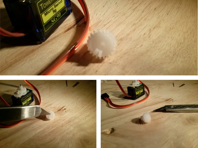
Be very careful with your hands and fingers because the gear is small and difficult to hold on to while cutting. Take your time, and don't rush through this step. Take a little material off at a time to reduce the amount of force needed.
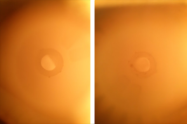
Next, look closely at the hole that this topmost gear fits onto the shaft with. It is a semicircle. To make sure it spins freely on the shaft 360 degrees, we need to auger out material to make it a full circle. Using an approximately 1.4mm jeweler's screwdriver, slowly twist it until the hole becomes circular.
Step 3: Remove All the Gears and Glue the Potentiometer
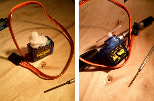
Remove the rest of the gears. Keep the servo sitting up and support it with something if necessary for this next step. Get your pliers (though you could use your fingers if you are very dexterous), and twist the shaft of the potentiometer. You will notice its 180 degrees of rotation to the left and right. Twist it back and forth a few times to get an idea of where center is, then leave it as close to center as you can.

Next, you need to carefully apply some superglue around the base (not on the shaft) of the potentiometer. Give it some time to dry. Gently blow on it and if you see the glue moving, it isn’t dry yet. If you were careless when gluing and assembling the servo while it is still wet, you might glue everything together! Disaster!
Step 4: Reassemble the Servo
Once the superglue is fully dried, using the picture we took at the beginning after removing the case, we can reassemble the gears carefully. Place the top cover of the casing back on, making sure it is securely and properly fitted in place. Then screw the case closed with the four screws removed in Step 1.
Step 5: Testing Your New Continuous Servo
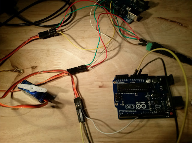
Now that you have everything put back together, it’s time to test the servo and make sure the conversion was successful. An Arduino is perfect for this and all you need to test it is your Arduino (we’re using an UNO board), 3 jumper wires, and a USB cable to connect the UNO to our computer. On our servos, the brown cable is ground, red is positive, and orange is for the signal. Connect ground to GND on your Arduino, postive to 5V on your Arduino, and the signal wire to pin 9 on your Arduino. (Note: A servo under any kind of load should not be hooked up to your Arduino like this, it could overdraw amps and cause your Arduino to reset or burn it out. But here we are just testing rotation, and just for a short time.)
We typed in and uploaded the following code:
//Test continuous servo conversion
#include Servo myservo;
void setup() {
myservo.attach(9);
}
void loop() {
myservo.write(180); //clockwise rotation
delay(2000); //rotation duration in ms
myservo.detach(); //detach servo to prevent “creeping” effect
delay(500); //short pause
myservo.attach(9); //reattach servo to pin 9
myservo.write(0); //counterclockwise rotation
delay(2000); //rotation duration in ms
myservo.detach(); //detach servo to prevent “creeping” effect
delay(500); //short pause myservo.attach(9); //reattach servo to pin 9 before looping
}
180 causes your servo to spin clockwise at full speed. 0 causes it to spin counterclockwise at full speed. Values of 45 and 135, for example, have the servo spin slower in their respective directions while 90 theoretically should keep the servo at rest. However, we say “theoretically” because the servo is never really perfectly centered. This causes the servo to creep ever so slowly in one direction or another. Besides being annoying it also ruins the accuracy of your project. So to prevent this creeping, we attach and detach the servo when necessary in the above Arduino code. Detaching it leaves it unpowered and therefore completely at rest.
Closing Thoughts
Now you have a continuously rotating servo that you can use alone for various projects, or pair up to power a robot or anything else you can imagine. There are definitely many other ways to do this particular hack. And there are obviously many better options you can use if you have the time and money to source them than a hacked continuously rotating servo. But in case you have a bunch lying around and want a quick solution, here it is.
We've used this hack for robots, an automatic fish feeder, and more recently, our 3D printed electric screwdiver. Just be careful with the final position of the potentiometer before gluing. If you didn't center it, the whole hack will fail. Good luck!
Follow ProgressTH.org on Facebook here, Instagram here, or on Twitter here. We also put all of our 3D printed models online for free at Thingiverse.com here.
Once the superglue is fully dried, using the picture we took at the beginning after removing the case, we can reassemble the gears carefully. Place the top cover of the casing back on, making sure it is securely and properly fitted in place. Then screw the case closed with the four screws removed in Step 1.

Step 5: Testing Your New Continuous Servo
Now that you have everything put back together, it’s time to test the servo and make sure the conversion was successful. An Arduino is perfect for this and all you need to test it is your Arduino (we’re using an UNO board), 3 jumper wires, and a USB cable to connect the UNO to our computer. On our servos, the brown cable is ground, red is positive, and orange is for the signal. Connect ground to GND on your Arduino, postive to 5V on your Arduino, and the signal wire to pin 9 on your Arduino. (Note: A servo under any kind of load should not be hooked up to your Arduino like this, it could overdraw amps and cause your Arduino to reset or burn it out. But here we are just testing rotation, and just for a short time.)

We typed in and uploaded the following code:
//Test continuous servo conversion
#include Servo myservo;
void setup() {
myservo.attach(9);
}
void loop() {
myservo.write(180); //clockwise rotation
delay(2000); //rotation duration in ms
myservo.detach(); //detach servo to prevent “creeping” effect
delay(500); //short pause
myservo.attach(9); //reattach servo to pin 9
myservo.write(0); //counterclockwise rotation
delay(2000); //rotation duration in ms
myservo.detach(); //detach servo to prevent “creeping” effect
delay(500); //short pause myservo.attach(9); //reattach servo to pin 9 before looping
}
180 causes your servo to spin clockwise at full speed. 0 causes it to spin counterclockwise at full speed. Values of 45 and 135, for example, have the servo spin slower in their respective directions while 90 theoretically should keep the servo at rest. However, we say “theoretically” because the servo is never really perfectly centered. This causes the servo to creep ever so slowly in one direction or another. Besides being annoying it also ruins the accuracy of your project. So to prevent this creeping, we attach and detach the servo when necessary in the above Arduino code. Detaching it leaves it unpowered and therefore completely at rest.
Closing Thoughts
Now you have a continuously rotating servo that you can use alone for various projects, or pair up to power a robot or anything else you can imagine. There are definitely many other ways to do this particular hack. And there are obviously many better options you can use if you have the time and money to source them than a hacked continuously rotating servo. But in case you have a bunch lying around and want a quick solution, here it is.
We've used this hack for robots, an automatic fish feeder, and more recently, our 3D printed electric screwdiver. Just be careful with the final position of the potentiometer before gluing. If you didn't center it, the whole hack will fail. Good luck!
Follow ProgressTH.org on Facebook here, Instagram here, or on Twitter here. We also put all of our 3D printed models online for free at Thingiverse.com here.